This document shows the main steps of the installation of Organica Biomodules into the reactors in pictures. This document is an installation guide; for the assembly of the Organica Biomodules and detailed technical information please refer to the Installation Manual for Organica Biomodule.
For safety reasons the assembly of the Organica Biomodules must be carried out by two people.
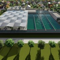
1. General Layout of a Standard FCR Reactor
The figure bellow shows the Organica Biomodules in the reactor. The Organica Biomodule comprises carrier units and plant racks. The parts of the plant rack and carrier unit is described in the Organica Biomodule Product Specification. The concrete beams, eye nuts, fastening elements and plants with supporting mesh are NOT part of the product, but they are necessary supplementary elements of it.

2. Installation
2.1 Installation of the Carrier unit
1st installation step – Screwing the C profile A-s onto the concrete beams
Screw the C profile A-s onto the concrete beams. The arrangement of the C profile A-s depends on the civil design that is tailored to the particular project and comes only after the design is finalised.
2nd installation step – Positioning the carrier unit
Position the carrier frame with two biofiber media units assembled onto it between the concrete support beams and above the eyenuts on the bottom of the reactor using a workshop crane.
Assembly of the carrier frame is explained in the Installation Manual for Organica Biomodule.
Assembly of the biofiber media units onto the carrier frame is explained in the Assembly Manual for Organica Biomodule Carrier Unit.

3rd installation step – Fastening of the carrier unit
Fasten the carrier frame to the C-profile. Then, start letting the biofiber media units down using the ropes provided.

4th installation step – Fixing the ropes
Thread the bottom end of the vertical ropes through the eyenuts on the bottom of the reactor. Fasten the bottom end of the vertical ropes to the corner straps at the bottom of the biofiber media units. The vertical ropes on the two neighbouring corners of the biofiber media units in the middle part of the carrier frame are to be threaded through one eyenut. Fasten the upper end of the vertical stretching ropes to the C profile A.

5th installation step – Placing the covers
Final vertical stretching is achieved by screwing down the hex nuts on the top of the threaded rods on the carrier frame. Installation of carrier units is finished when the covers are placed above them.

2.2 Installation of the Plant Rack
1st installation step – Screwing the C profile B-s onto the concrete beams
Screw the C profile B-s onto the concrete beams. The arrangement of the C profile B-s depends on the civil design that is tailored to the particular project and comes only after the design is finalised.
2nd installation step – Positioning the basket
Position the basket between the concrete support beams using a workshop crane. Assembly of the plant rack is explained in the Installation Manual for Organica Biomodule in detail.

3rd installation step – Fastening of the plant rack
Hang the plant rack on the square hollow section and fix it with the fastening elements provided.

Installation of plant racks and carrier units are independent from each other; however, for safety reasons it is advised to continue installation sequentially according to the architectural plans.
Once the Organica Biomodule installation has finished plantation works can start.
3. Maintenance
3.1 Replacement of Aeration Diffusers
Installed biomodules have no effect on the aeration diffusers. After installation of biomodules the aeration diffusers are still easily accessible by lifting the biofiber media units without removing them.